Products
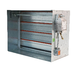
Airfoil Blade Combination Fire & Smoke Dampers 

-
Product Information
FSD-AF and F/S-AFM is a series of CVS-SAFE4 UL/ULC classified combination fire & smoke dampers manufactured with “Airfoil” type blades. These dampers have been investigated for fire protection rating of 1-1/2-hour or 3-hour (UL555) and at minimum velocities of 2000 feet per minute at 4 in. w.g. of static pressure for the range of “3V” blade models and maximum velocities of 4000 feet per minute at 6 in. w.g. of static pressure for the range of “Airfoil” blade models for a leakage rating as defined under Class I or Class II (UL555S).
-
Submittals

FSD-AF-211 – 1.5 Hour, Class I, Airfoil Blade Combination Fire & Smoke Damper

FSD-AF-212 – 1.5 Hour, Class II, Airfoil Blade Combination Fire & Smoke Damper

FSD-AF-231 – 3 Hour, Class I, Airfoil Blade Combination Fire & Smoke Damper

FSD-AF-232 – 3 Hour, Class II, Airfoil Blade Combination Fire & Smoke Damper

F/S-AFM-PB-I & F/S-AFM-OB-I – Modulating, 1.5 Hour, Class I, Parallel or Opposed Airfoil Blade Combination Fire & Smoke Damper

F/S-AFM-PB-II & F/S-AFM-OB-II – Modulating, 1.5 Hour, Class II, Parallel or Opposed Airfoil Blade Combination Fire & Smoke Damper

F/S-AFM-PB-3-I & F/S-AFM-OB-3-I – Modulating, 3 Hour, Class I, Parallel or Opposed Airfoil Blade Combination Fire & Smoke Damper

F/S-AFM-PB-3-II & F/S-AFM-OB-3-II – Modulating, 3 Hour, Class II, Parallel or Opposed Airfoil Blade Combination Fire & Smoke Damper

FSD-AF-FA-211 – Front Access, 1.5 Hour, Class I, Airfoil Blade Combination Fire & Smoke Damper

FSD-AF-FA-212 –Front Access, 1.5 Hour, Class II, Airfoil Blade Combination Fire & Smoke Damper

FSD-AF-OW-211 – Out-of-Wall, 1.5 Hour, Class I, Airfoil Blade Combination Fire & Smoke Damper

FSD-AF-OW-212 – Out-of-Wall, 1.5 Hour, Class II, Airfoil Blade Combination Fire & Smoke Damper
-
Performance Data

FSD-AF-211 – 1.5 Hour, Class I, Airfoil Blade Combination Fire & Smoke Damper

FSD-AF-212 – 1.5 Hour, Class II, Airfoil Blade Combination Fire & Smoke Damper

FSD-AF-231 – 3 Hour, Class I, Airfoil Blade Combination Fire & Smoke Damper

FSD-AF-232 – 3 Hour, Class II, Airfoil Blade Combination Fire & Smoke Damper

F/S-AFM-PB-I & F/S-AFM-OB-I – Modulating, 1.5 Hour, Class I, Parallel or Opposed Airfoil Blade Combination Fire & Smoke Damper

F/S-AFM-PB-II & F/S-AFM-OB-II – Modulating, 1.5 Hour, Class II, Parallel or Opposed Airfoil Blade Combination Fire & Smoke Damper

F/S-AFM-PB-3-I & F/S-AFM-OB-3-I – Modulating, 3 Hour, Class I, Parallel or Opposed Airfoil Blade Combination Fire & Smoke Damper

F/S-AFM-PB-3-II & F/S-AFM-OB-3-II – Modulating, 3 Hour, Class II, Parallel or Opposed Airfoil Blade Combination Fire & Smoke Damper

FSD-AF-FA-211 – Front Access, 1.5 Hour, Class I, Airfoil Blade Combination Fire & Smoke Damper

FSD-AF-FA-212 –Front Access, 1.5 Hour, Class II, Airfoil Blade Combination Fire & Smoke Damper

FSD-AF-OW-211 – Out-of-Wall, 1.5 Hour, Class I, Airfoil Blade Combination Fire & Smoke Damper

FSD-AF-OW-212 – Out-of-Wall, 1.5 Hour, Class II, Airfoil Blade Combination Fire & Smoke Damper
-
Specifications

FSD-AF – Airfoil Blade Combination Fire & Smoke Damper

F/S-AFM – Modulating, Parallel or Opposed Airfoil Blade Combination Fire & Smoke Damper

FSD-AF-FA – Front Access, Airfoil Blade Combination Fire & Smoke Damper

FSD-AF-OW – Out-of-Wall, Airfoil Blade Combination Fire & Smoke Damper
-
Installation

FSD – Combination Fire & Smoke Damper Installation, Operation & Maintenance

FSD-OW, FSD-FA – Out of Wall and Front Access, Fire and Combination Fire & Smoke Damper Installation, Operation & Maintenance

Installing Fire and Combination Fire & Smoke Dampers in a Shaft Wall Installation Supplement

Framing Requirements for Wood or Steel Stud Walls Installation Supplement

UL-Approved Breakaway Duct Connections Installation Supplement

Optional Sealing of Dampers in Fire and Smoke Rated Walls or Floors Installation Supplement

Fabrication & Installation of Support Mullions Installation Supplement

Field Modification of Factory Supplied Sleeves Installation Supplement

Installing Fire and Combination Fire & Smoke Dampers in Concrete Floor with Steel Deck Installation Supplement

Actuator Reference Chart

Actuator to Fire Alarm Control Panel/BMS Wiring Diagrams for 24 VAC Power Supply

Modulating Actuator to Fire Alarm Control Panel/BMS Wiring Diagrams for 24 VAC Power Supply (for AFM Models only)

Actuator to Fire Alarm Control Panel/BMS Wiring Diagrams for 120 VAC Power Supply

Actuator to Fire Alarm Control Panel/BMS Wiring Diagrams for 230 VAC Power Supply

Blade Switch Package
-
Info/ Brochures

CVS Product Brochure

